Connecting NSX-T Tier 0 Gateway to another Tier 0 Gateway
Reference : NSX-T Design Guide
A Tier 0 Gateway is typically required to connect to the physical network.
A Tier 1 Gateway in NSX-T does not connect to the physical network directly.
Segments to which workloads are attached are connected to Tier 1 Gateways.
Tier 0 Gateway is called a provider gateway and Tier 1 Gateway is called as tenant gateway.
In this post, we will explore the configurations required to connect NSX-T Tier 0 Gateway to another Tier 0 Gateway.
This addresses the use case where multiple Tier 0 Gateways need to connect to one Tier 0 Gateway which can possibly consist of 8 Edge Nodes for 8 way ECMP.
This addresses the use case where multiple Tier 0 Gateways need to connect to one Tier 0 Gateway which can possibly consist of 8 Edge Nodes for 8 way ECMP.
One may note that it is possible to use Active-Active or Active-Standby availability mode on the Tier 0 Gateway.
In this lab set up, both the Tier 0 Gateways have been configured in Active-Active High Availability mode.
 |
| Lab Topology |
As shown in the figure above, two Tier 0 Gateways have been created using four edge node VMs.
Tier 0 Gateways are named as Tier 0 Gateway Up and Tier 0 Gateway Down respectively.
A Tier 1 Gateway is connected to Tier 0 Gateway Down.
A segment is attached to this Tier 1 Gateway with a corresponding subnet of 172.16.10.0 / 24
Physical routers upstream connect via VLANs to the the edge node VMs.
 |
| IP Addressing and BGP Diagram |
The above diagram shows the IP addressing used in this lab topology along with the BGP Peerings.
BGP AS Number 65000 is used on the Tier 0 Gateways.
BGP AS number 65001 is used on the physical routers.
The physical routers are advertising default routes towards the NSX edges.
NSX-T Fabric Preparation:
 |
| Transport Zones |
Edge Transport Nodes corresponding to edge cluster used for Tier 0 Gateway Down will only have the Overlay Transport Zone.
Edge Transport Nodes corresponding to edge cluster used for Tier 0 Gateway Up will have overlay transport zone, VLAN-1 transport zone and VLAN-2 transport zone.
 |
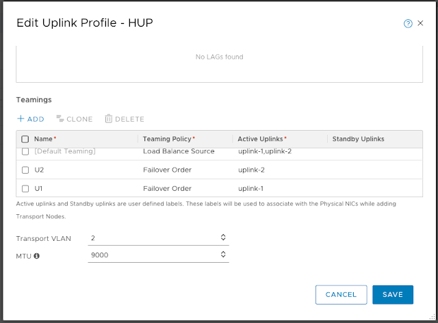
| Uplink Profile for Edge Node VMs |
The uplink profile for edge has VLAN ID as 4 which is for Tunnel Endpoint TEP Interfaces on the edge node VMs.
Tunnel Endpoint interfaces on Transport Nodes are used to establish Geneve tunnels between each other.
The VLAN ID 2 for TEP interfaces on compute hosts is different because the edge node VMs of Tier 0 Gateway Up use the N-VDS of compute for connectivity.
 |
| Uplink Profile for Compute Hosts |
Note the VLAN ID in this compute uplink profile is set as 2
 |
| Compute Host Transport Nodes |
Compute Host Transport Nodes are prepared as above.
ESXi transport zone is VLAN backed transport zone used to host VLAN backed segments. VLAN backed segments have been used to attach to fast path interfaces of edge node VM.
This has been covered in my post here.
 |
| Edge Transport Nodes |
 |
| Edge Cluster for Tier 0 Gateway Up |
 |
| Edge Cluster for Tier 0 Gateway Down |
Gateway and Interface Configuration:
 |
| Tier 0 Gateways |
T0 DOWN
T0 UP
 | |
| Segments used for connecting Tier 0 Gateways to each other |
Overlay backed transport zone is used to create four overlay segments and these segments will be used for connecting the Tier 0 Gateways to each other as shown in the lab topology earlier.
 |
| Layer 3 interface configurations on Tier 0 Gateway Up |
 |
| Layer 3 interface configurations on Tier 0 Gateway Up (Note the edge nodes used) |
 |
| Layer 3 interface configurations on Tier 0 Gateway Down |
Routing Configuration:
BGP configuration is done next on the physical routers and the Tier 0 Gateways.
Please follow the BGP diagram above for the BGP peerings.
Source Addresses are used to source BGP session from appropriate interface only.
 |
| BGP Neighbor Configuration on Tier 0 Gateway Down |
 |
| BGP Neighbor Configuration on Tier 0 Gateway Up |
 |
| Distributed Router only Tier 1 Gateway with no edge cluster association |
Connected routes on Tier 1 Gateway are advertised towards upstream Tier 0 Gateway Down.
 |
| Redistribute connected interfaces and segments on Tier 0 Gateway Down |
 |
| Redistribute connected interfaces and segments on Tier 0 Gateway Up |
Validation:
 |
| BGP peering on TOR2 physical router |
 |
| BGP Peerings on Edge Node VM 1 which belongs to Tier 0 Gateway Up |
Notice that there is BGP peering between two edge nodes which are forming the Tier 0 Gateway, this is because we have enabled Inter SR iBGP
This IP 172.16.10.1 is configured as gateway for the segment attached to Tier 1 Logical Router.

