NSX-T Routing
References:
Before we discuss the routing part, it is essential to cover key topics related to NSX-T
1. N-VDS
2. Transport Zone
3. Compute Host Transport Nodes
4. Edge Transport Nodes
1. N-VDS
Is responsible for switching packets and is responsible for forwarding traffic between VMs or between VMs and the physical network.
When you define a transport zone (explained below), you essentially also define a N-VDS.
You can use the same N-VDS for Overlay as well as for VLAN.
N-VDS' are instantiated on compute host transport nodes and edge transport nodes.
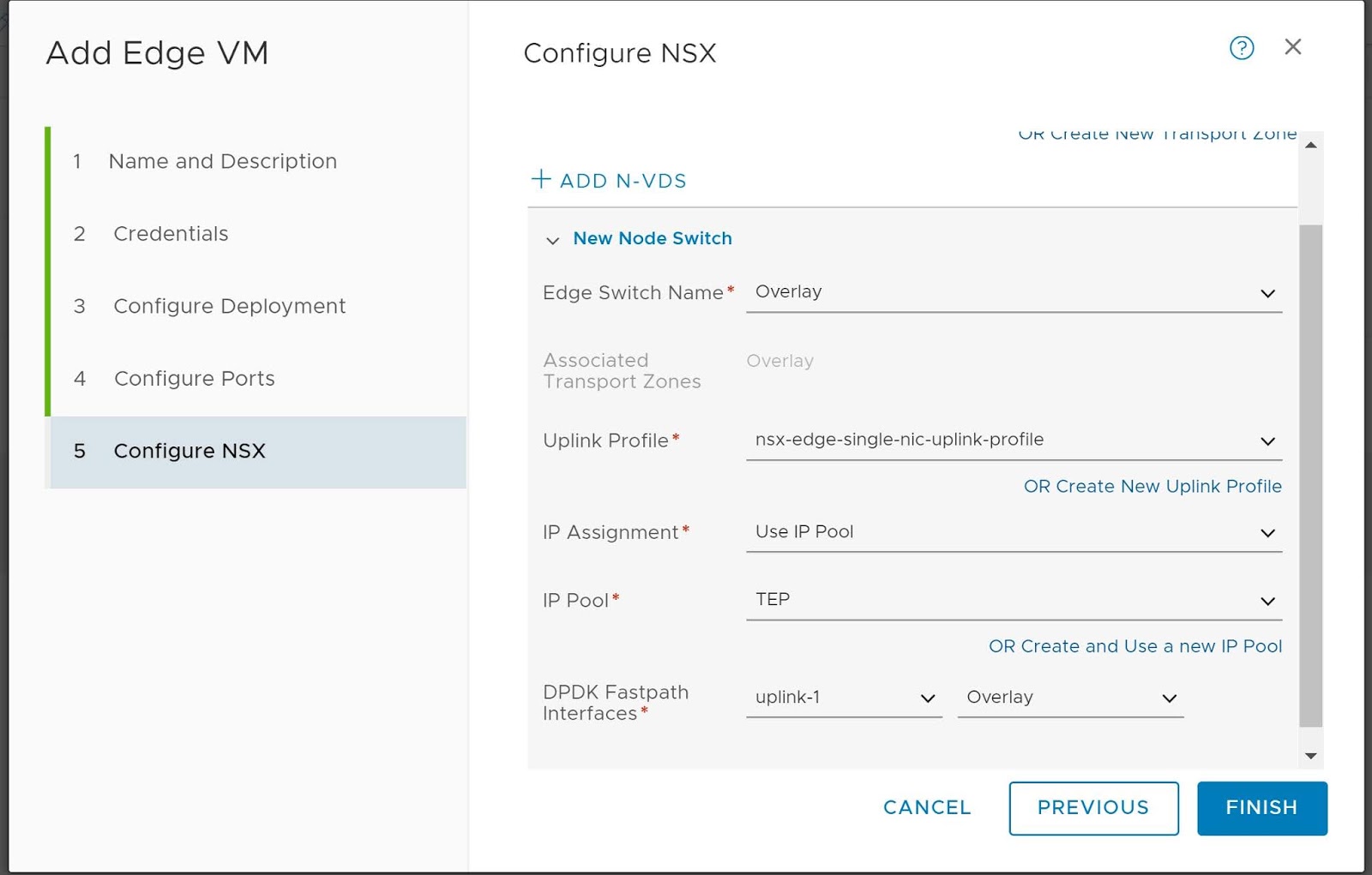
Uplink profiles in NSX-T mention the teaming policies. Source port ID and failover order are the two teaming policies supported in NSX-T.
While configuring N-VDS parameters, you are able to specify the appropriate uplink profile.
2. Transport Zone
Transport Zone defines the span of a segment. Segment could be thought of a Logical Switch which is based on Geneve encapsulation.
You are able to select transport zones during the configuration of compute host transport nodes and edge transport nodes.
3. Compute Host Transport Nodes
These are hypervisors which are prepared for NSX-T
Currently, there is support for KVM and ESXi based hypervisors.
The Compute Host Transport Nodes will host the workloads/VMs for the different application tiers viz. Web, App and DB.
 |
| Compute Host Transport Node Connectivity |
In the figure above, source port ID based teaming policy has been used.
Physical nics 3 and 4 are used for N-VDS whereas nics 1 and 2 are used for services on VDS - management, vmotion and storage.
4. Edge Transport Nodes
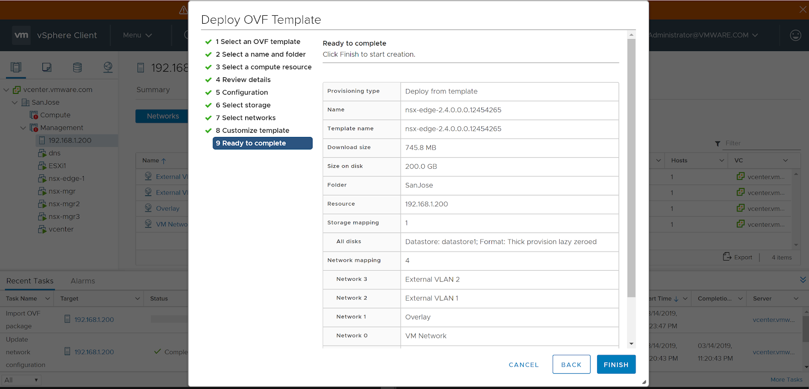
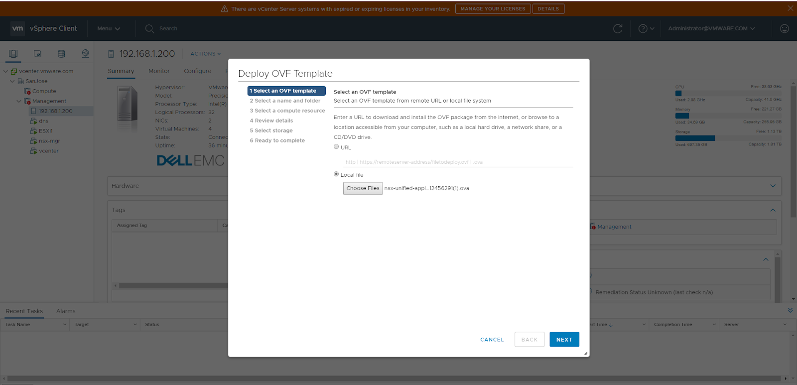
Come in VM form factor and baremetal.
They are required for connectivity with physical network and also when services like NAT, edge firewall are enabled on Tier 0 or Tier 1 Logical Routers.
In case the Edge Transport Nodes are of VM form factor, they could possibly be hosted on hosts which are not prepared for NSX-T.
 |
| Edge Transport Node VM Connectivity |
The above diagram shows:
1. Two Edge Node VMs on a single ESXi host.
2. Each Edge Node VM has four nics which are fast path interfaces.
VNIC 1 is used for management
VNIC 2 is used for peering with the physical network using VLAN 1
VNIC 3 is used for peering with the physical network using VLAN 2
VNIC 4 is used for Overlay/TEP Tunnel End Point traffic.
3. Each of these nics are associated with a corresponding Distributed Port Group on the VDS as shown in the figure.
EXT 1 and EXT 2 port groups are used for VLANs 1 and 2 respectively.
TEP port group is used for Overlay traffic.
4. Based on the teaming policies of the distributed port groups, traffic is pinned appropriately towards each of the physical nics on the ESXi host.
===============================================
NSX-T Routing has a two tier architecture
a. Tier 0 Logical Router
Typically owned by the provider.
Multiple Tier 1 Logical Routers connect to the Tier 0 Logical Router.
Tier 0 Logical Router then connects to the physical network upstream.
b. Tier 1 Logical Router
Typically owned by the tenant.
VMs are connected to Tier 1 Logical Router or a Tier 0 Logical Router using segments.
Segments can be overlay backed or VLAN backed.
In the diagram above, LIF 1, LIF 2 and LIF 3 are downlinks
Tier 1 Logical Router and Tier 0 Logical Router are connected using a Routerlink.
This routerlink has IP addressing in the range of 100.64.0.0 / 10 (RFC6598)
Tier 0 Logical Router connects to the physical network using uplink.
This uplink supports static routing and BGP routing.
Equal Cost Multi Pathing is supported for both static and BGP.
There is no routing protocol between Tier 0 Logical Router and Tier 1 Logical Router.
=================================================
The diagram above shows a Tier 0 Logical Router and a Tier 1 Logical Router along with the various links - Uplink, Routerlink and Downlinks.
Both of these logical routers can be further broken into a Services Router SR and Distributed Router DR.
A logical router LR in the context of NSX-T is mainly composed of:
a. Services Router SR
b. Distributed Router DR
a. Services Router SR
Services Router SR is used for centralized services like
- Connectivity to the physical network
- Load Balancing
- NAT
- Edge Firewall
Services Router SR require Edge Transport Nodes which come in the form of VM or baremetal.
These Edge Transport Nodes come into the picture if services are enabled on Tier 0 Logical Router or Tier 1 Logical Router.
b. Distributed Router DR
Distributed Router DR is similar to Distributed Logical Router in NSX-V
This provides in kernel distributed routing on the hypervisor which prevents hair pinning and takes care of East-West traffic in the Data Center. Distributed Routing also provides routing closest to the source.
Distributed Routing provides line rate of traffic.
===============================================
Traffic Flows
We now cover traffic flows (east-west and north-south) in context of Tier 0 and Tier 1 Logical Routers, SR and DR.
 |
| Logical Layout for Traffic Flow |
 |
| Traffic flow from Source VM to Destination VM |
As shown in the figure above, the logical traffic flow goes through Tier 1 Logical Router of Tenant 1 which then forwards to Tier 0 Logical Router.
Tier 0 Logical Router forwards the traffic to Tier 1 Logical Router of Tenant 2.
Then the traffic is forwarded by the local router to the VM.
Take a note here that a centralized service is enabled on Tier 1 Logical Router of Tenant 1.
Keeping this in mind, now lets take a look at the traffic flow from SR and DR perspective.
 |
| East West Traffic Flow from Source VM to Destination VM |
As explained before, TEP interfaces are created on Host Transport Nodes as well as on Edge Transport nodes.
In the figure above, source VM and destination VM reside on a compute host which is prepared for NSX-T.
As such, this is a Host Transport Node.
Tier 0 SRs in diagram above are serving in Active-Active/ECMP mode.
Tier 1 SRs in diagram above are in Active/Standby mode.
A key point to note is that DRs are created or instantiated on all Transport Nodes.
SRs only reside on edge transport nodes which are in NSX-T edge node clusters.
Hence in the topology above, you do not see SRs on the compute host.
The topology above has two edge node clusters:
Blue - Edge Node Cluster for North-South physical connectivity with the network. For peering with Cisco ACI.
Red - Edge Node Cluster for centralized services like a CSP port, edge firewall, NAT.
As you can see in the diagram, Tier 1 DR of Tenant 1 routes the traffic from source VM before it is Geneve encapsulated and sent across to the TEP interface of Edge Node VM 3.
Tier 1 SR of Tenant 1 then forwards the traffic to Tier 0 DR.
Since the traffic is not destined to the physical network, the traffic is routed by Tier 0 DR to the Tier 1 DR of Tenant 2.
Tier 1 DR of Tenant 2 determines that destination VM is connected to a local segment. Hence traffic is then Geneve encapsulated by TEP interface on Edge Node VM 3 and sent across to TEP interface of compute host. Then the packet is delivered to destination VM.
The same logic is applied for return traffic from destination VM to source VM resulting in below typologies.
 |
| East West Traffic flow from destination VM to source VM |
North - South traffic flows are covered in diagrams below.
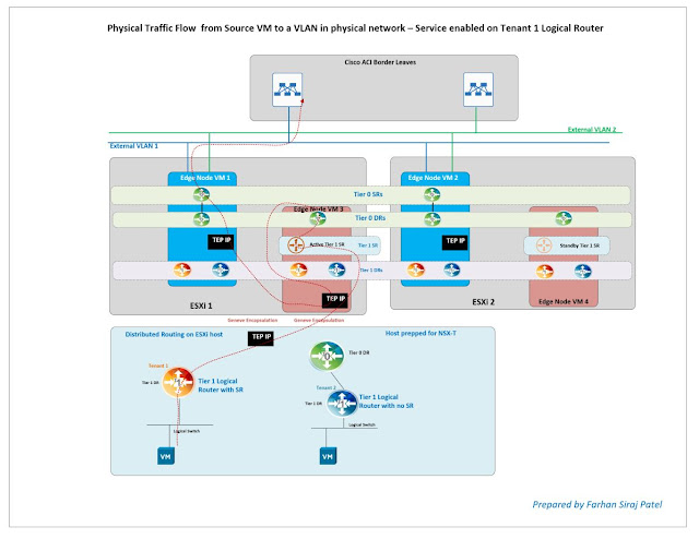 |
| North - South traffic flow from source VM towards the physical network |
 |
| North - South traffic flow from physical network towards a VM on compute host prepared for NSX-T |