 |
| Cross Vcenter NSX using Local Egress |
The above topology has been used for the purpose of this lab.
In this blog post, we are going to cover Active Active Cross Vcenter NSX.
BGP is used as a routing protocol in this setup above.
And appropriate BGP peerings have been illustrated in topology above.
We are using eBGP between NSX edge and physical router.
iBGP is used within NSX between NSX edge and UDLR.
Notice the connectivity using Transit LS in both sites.
A separate Logical Switch is used in Site 2 between UDLR and NSX edge.
In my previous blogs on Cross Vcenter NSX using BGP and Cross Vcenter NSX using OSPF, we did not cover local egress feature of UDLR.
With local egress enabled, UDLR Control VMs are deployed in both the sites - Site 1 and Site 2.
There's a parameter called Locale ID which controls the routes being advertised to the hosts in each site.
Site specific Locale ID is associated with the routes.
Routes learnt from edges by the UDLR are sent to the Universal Controller Cluster and from there on to the hosts.
With Locale ID, hosts in Site A will forward egress traffic towards the NSX edges in Site A.
Likewise for Site B.
Traffic sourced from the physical network and destined for subnets behind UDLR (UDLR being deployed using local egress) can reach the UDLR via Site A NSX edge or via Site B NSX edge.
Essentially, asymmetric routing takes place and there is no deterministic traffic flow.
Also, if you have firewalls upstream to the NSX edges in each of the sites, then the firewall will drop such asymmetric traffic.
Firewall can receive SYN-ACK when it has not seen the SYN packet for a specific TCP session.
So one should be careful and not use Local Egress in such a situation where there are firewalls upstream to NSX edges.
Now let's see how a UDLR is deployed using Local Egress.

The important thing when you want to enable Local Egress on the UDLR is to ensure that we select this option while deploying UDLR itself.

 Select cluster and datastore
 We will do the interface configurations later.

Click on Finish to start deploying the UDLR.
Verify that Local Egress is enabled on the UDLR

=======================================================================
Routing configurations of Site A
Below are the interface configurations of UDLR.
Routing configurations are applied as per our topology above.
1. BGP AS number 65001 is used for Site A and BGP AS 65011 is used for Site B.
2. We will see from interface configurations of UDLR in Site B that we are unable to edit the interface configurations there.
 | ||||||
| Interface Configurations of UDLR under Primary NSX Manager |


 |
| UDLR Control VM of Site A |
========================================================================
Routing configs of Site B
 |
| Unable to edit interface configurations of UDLR from Secondary NSX Manager |


 |
| UDLR Control VM is deployed in Site B as well |
========================================================================
Verification and traffic flows
We are going to do a trace from a web server which is hosted on a cluster of Site B.

 |
| Egress Traffic from Web Server in Site 2 towards 192.168.100.0/24 in physical network |
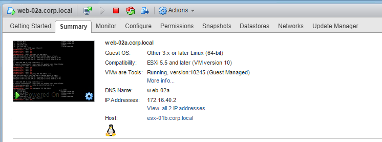 |
| Web server hosted on a cluster of Site B |
Below trace from web server on cluster of Site B shows that egress traffic is via Site B.
 |
| Trace goes via Site B |
 |
| Route lookup on the physical router |
Best path from the output above is via Site 1
Let's also vmotion the web server and bring it back to a cluster in Site 1.
Then we'll verify the trace from the web server towards the physical network.
 |
| Web Server vmotioned to Site 1 |
 |
| Trace goes via Site 1 because Local Egress is enabled |
Notice from the trace above, that now the trace goes via Site 1
No comments:
Post a Comment