Showing posts with label NSX. Show all posts

Friday, June 26, 2020

NSX-V to NSX-T Migration using Layer 2 Bridging

NSX-V to NSX-T Migration using Layer 2 Bridging

This blog will explore how we can migrate workloads which are on hosts prepared for NSX-V to hosts prepared for NSX-T using NSX-T Layer 2 Bridging.


Cluster Setup

In the lab setup, four hosts ESXi 1 up to 4 are prepared for NSX-T and the remaining four hosts ESXi5 up to ESXi 8 are prepared for NSX-V

NSX-T edges used for Layer 2 bridging are on NSX-V prepared hosts.


Logical Setup

The above is the logical setup used in this lab.


IP Addressing

Above shows the IP addressing used in the lab.


BGP AS Numbering

The above picture shows the BGP AS numbering used.


BGP peerings

The above diagram shows the BGP peerings.

e-BGP peerings between NSX and the physical network.

i BGP between NSX-V edges and Distributed Logical Router.

There is no routing protocol between Tier 1 Gateway of NSX-T and Tier 0 Gateway upstream.

During migration, traffic flow will be through NSX-V edges which means that:

1. You can prefer not to advertise connected subnets on the Tier 1 Gateway

2. Or to keep BGP disabled on Tier 0 Gateway.


NSX-V Setup

NSX-V Prepared Cluster

Above picture shows the four hosts prepared for NSX-V


NSX-V Edges and DLR

The required NSX-V edges and DLR have been deployed.


Workloads hosted on both clusters


VM on VXLAN

One VM Windows 10-2 is hosted on this NSX-V prepared cluster.


We need to make sure that security settings of the port group (corresponding to the VXLAN being bridged) are set accordingly.

  • Set promiscuous mode on the portgroup.
  • Allow forged transmit on the portgroup.

https://docs.vmware.com/en/VMware-NSX-T-Data-Center/2.5/administration/GUID-F133B293-5DEA-4DC8-99DB-6EF004C8D8D7.html

Security settings of VXLAN backed port group


NSX-T Setup

Overlay Transport Zone defined using REST API Client

To ensure unique mac addresses are used on layer 3 interfaces of DLR and Tier 1 Gateway respectively, ensure overlay transport zone in NSX-T is defined as above with

"nested_nsx": true


Compute host transport nodes prepared for NSX-T

NSX-T Edges

nsx-edge-1 and nsx-edge-2 are NSX-T edges which are used for Layer 2 bridging.
These edges are placed on cluster prepared for NSX-V.

The remaining two edges nsx-edge-3 & nsx-edge-4 are used for Tier 0 Gateway.


Edge used for L2 Bridging

Fast-path interfaces fp-eth0 and fp-eth1 on the edges used for Layer 2 bridging are used for Geneve traffic, they are uplinked to a trunk port group on VDS used for NSX-V preparation. This way all NSX traffic stays on this VDS which is also used for NSX-V host preparation.


NSX-T Edge Clusters

Tier 0 Gateway

Tier 1 Gateway

NSX-T Segment connected to Tier 1 Gateway

Gateway set on NSX-T Segment

Validation of the setup

VM on NSX-T Segment


Reach ability between physical router loopback and both VMs

The above picture shows BGP peerings between the router and NSX-V edges.
At this stage, the BGP peerings between the physical routers and NSX-T edges are down/disabled.
Reason being that all workloads from NSX-V prepared hosts are not yet on NSX-T prepared hosts.

Reach ability between VM on VXLAN to loopback of physical router

Reach ability between VM on NSX-T segment to loopback of physical router

At this point, we know that Layer 2 bridging is working as intended and that the layer 2 bridge is forwarding traffic upstream.


Traffic flow from VM on NSX-T Segment to loopback interface of physical router

Migration

Now we will migrate the VM which is on NSX-V prepared cluster to NSX-T prepared cluster.

With this, both the workloads will then be on NSX-T prepared cluster.

At this point of time, we need to ensure that workloads have Tier 1 Gateway as their gateway.

We will ensure BGP peerings between physical routers and NSX-T edges are now all up.

And disable the BGP peerings between physical routers and NSX-V edges


Workloads migrated to NSX-T prepared cluster

Above picture shows that workloads have moved to NSX-T prepared cluster.


After migration, traffic flow from physical router to VMs on NSX-T segment

From the physical router, we validate that BGP peerings with NSX-T edges are now up and those with NSX-V edges are down.

Traffic now starts flowing through NSX-T edges.


VM on NSX-T Segment to loopback IP of physical router

VM on NSX-T segment to loopback IP of physical router

Traffic flow after migration

Thursday, August 23, 2018

NSX Edge Load Balancer - One Arm Mode


In the topology above, NSX edge load balancer is deployed in one arm mode.
NSX edge load balancer has a single layer 3 interface which is connected to Distributed Logical Router via a logical switch.
This logical switch is dedicated for Load Balancing Tier.

There is also a Web Tier hosting web servers and these web servers are connected to Distributed Logical Router via Web Tier logical switch.
Pool members corresponding to the virtual server are both residing on this Web Tier Logical switch.

The routing topology of this whole setup has already been covered in this post here.


The single vnic of NSX Edge Load Balancer has primary IP address as 172.16.20.100 / 24
The single vnic of NSX Edge Load Balancer also has secondary IP addresses assigned to it as below
Secondary IP 1 – 172.16.20.101
Secondary IP 2 – 172.16.20.102
We will be using one of these secondary IP addresses to create a virtual server.

=========================================

Configuration:

We will first enable the load balancer service on NSX Edge Services Gateway.
Enable Load Balancer Service


Application Profile
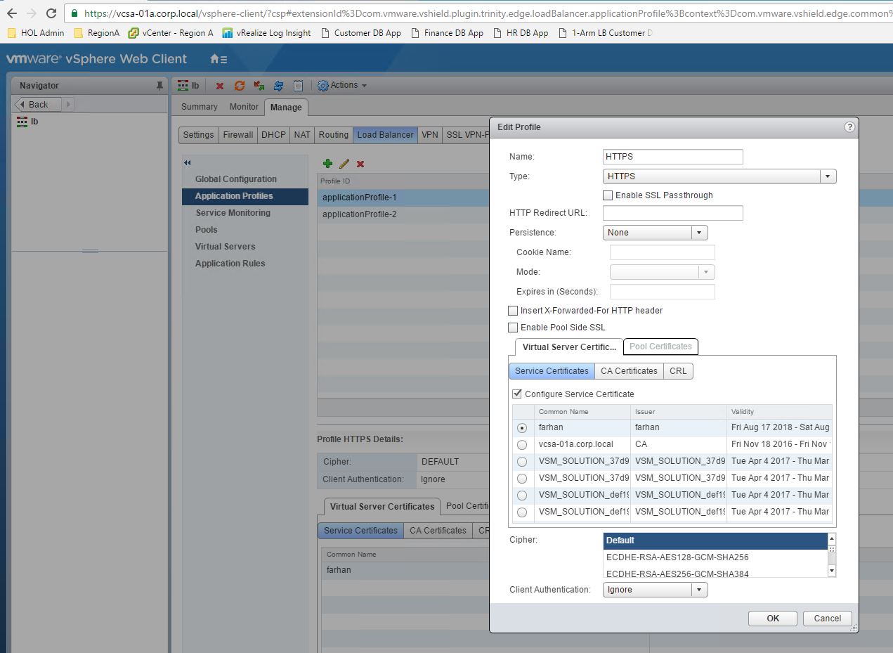
Application profile is created then and the details are as below
Application profile name - HTTPS
Application profile type – HTTPS
Certificate – For this lab setup, we have used a self-signed certificate.

Server Pool
Server pool is created as below
Pool name – pool
Algorithm – Round robin
Members – Virtual Machine web-01a, tcp/80
Members – Virtual Machine web-02a, tcp/80


Virtual Server

Virtual server is created using the secondary IP address and the virtual server details are as below
Virtual Server IP – 172.16.20.101
Virtual Server port – 443
Application Profile – HTTPS
Server pool name – pool

====================================


A management station is residing on the physical network with IP address as 192.168.110.10
We have also taken packet captures on the NSX Edge Load Balancer interface for below communications

  • Communication between the management station and the virtual server 172.16.20.101, tcp port 443
  • Communication between NSX Edge Load Balancer and the pool members.  


    Comm. between Mgmt. Station & Virtual Server


    Comm. between load balancer & pool members


It is worth noting that in the case when a secondary IP address 172.16.20.101 is assigned to single vnic of NSX Edge Load Balancer & the secondary IP address is used to create virtual server, the load balancer uses the primary IP address 172.16.20.100 to establish a connection between itself and the pool members.

Both the above packet captures are done at the same time while trying to access the web page at https://172.16.20.101
NSX Edge Load Balancer is working as a reverse proxy and from the packet captures, it is evident that there are two different TCP connections -
  1. One between initiator and load balancer 
  2. The other between load balancer and pool member
============================================================

NSX Edge Load Balancer supports below features:

1. SSL Offload
2. SSL Bridging
3. HTTP Profile with ‘insert X-Forwarded-For’
4. Cookie based persistence as well as source IP based persistence is supported.
5. Redirection from http to https
6. Multiple ciphers can be used.
7. Load balancing algorithms which are supported are:
  • Round robin
  • IP Hash
  • Least connection
  • URI
  • HTTPHEADER
  • URL 
=============================================================

Some very useful resources:

NSX Admin Guide
https://docs.vmware.com/en/VMware-NSX-for-vSphere/6.4/nsx_64_admin.pdf

NSX Reference Design Guide
https://www.vmware.com/content/dam/digitalmarketing/vmware/en/pdf/products/nsx/vmw-nsx-network-virtualization-design-guide.pdf