Showing posts with label load balancer. Show all posts

Saturday, March 14, 2020

Load Balancing in NSX-T


Load Balancing in NSX T

Reference:

This post covers the configuration required to use load balancer which is a native feature in NSX-T.

Pre requisites before configuring load balancer:

1. NSX T Manager Cluster should be deployed
2. Transport zones should be defined.
3. Uplink profiles should be created.
4. Hosts should be configured as Host Transport Nodes.
5. Edge Transport Nodes should be deployed and configured.
6. Edge Cluster should be created.
7. Tier 0 Gateway should be created and peering with physical network should be in place.

Logical Topology for Load Balancing

As shown in the above topology, one Tier 0 Gateway aggregates the connections from two Tier 1 Gateways.
There is one Tier 1 Gateway dedicated for load balancing service.
The other Tier 1 Gateway is where the workloads are connected via segments.
Tier 1 Logical Router 2 is a DR only Logical Router/Gateway to which workload segment is connected.

Tier 0 Gateway peers with the physical network and hence always requires edge cluster.
In this lab, we will use the same edge cluster for Tier 0 Gateway and for the Tier 1 Gateway used for load balancing service.

If sufficient resources exist, then dedicated resources can be provided for load balancing service and as such a separate edge cluster can be created which will be used only for services viz. load balancing.


DR only Tier 1 Gateway

As shown above, this Tier 1 Gateway is a DR only Tier 1 Gateway.
Segments for workloads are connected to this Tier 1 Gateway.
This Tier 1 Gateway is not associated with any edge cluster.

The DR only status of Tier 1 Gateway can also be verified using the below command on CLI of the edge node.

DR Only Tier 1 Gateway


The above Tier 1 Gateway is used for load balancing purpose.
Load balancing service requires presence of edge cluster.
As you can see, edge cluster is associated with this Tier 1 Gateway.
Also note that from route advertisement perspective, we are advertising LB VIP routes and LB SNAT IP Routes from this Tier 1 Gateway.
 
Communication between Virtual Server and the servers
The above diagram shows the communication between LB Virtual Server IP address 172.16.40.6 and the back end servers.
LB Virtual Server IP 172.16.40.6 is also used as SNAT IP address because the load balancer is in one arm mode. One arm mode of load balancer requires SNAT because the back end servers will then respond back to the SNAT IP.


Configuration of Load Balancer:

Here we are going to configure Layer 4 TCP based load balancing.

Server pool is defined as follows.
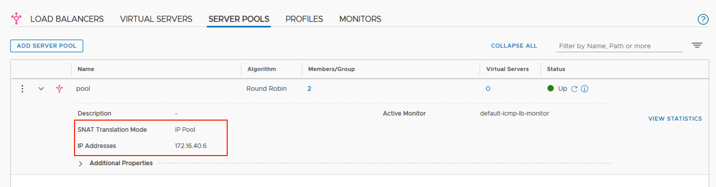
Server Pool Configuration

Server Pool Members
As shown above, server pool is created.
Please note that SNAT configuration has been applied while creating the server pool and the SNAT IP has been kept as the virtual server IP 172.16.40.6

Server pool members are configured.

Next, create a load balancer and associate Tier 1 Gateway 'T1-LB' with this load balancer.

Create load balancer
Note that the load balancer size here is kept as small, this is just for lab purpose.
We need to keep in mind the configuration maximums for each load balancer size.


Load balancer size depends upon the size of the edge node deployed.
If the size of the edge node is large, then one large sized load balancer can be created.
1000 virtual servers can be created for Large sized load balancer.

Next, create a virtual server.
Create Virtual Server


Associate Virtual Server with server pool

Status of Virtual Server
Using above, virtual server status can be verified using the UI.
 
Troubleshooting using CLI:


High Availability Status on Edge Node

Using the above commands, you can verify which edge node is 'Active'.
As seen, for the service router SR-T1-LB, edge node 'edgenode-01a' is Active.
 
You can get UUID of Load Balancer using the Advanced UI:
UUID of Load Balancer

Using this UUID, you can execute below commands on the Active edge node to display the server pool status and the status of virtual server.


Server Pool Members Information using CLI


Virtual Server Status and information


Thursday, August 23, 2018

NSX Edge Load Balancer - One Arm Mode


In the topology above, NSX edge load balancer is deployed in one arm mode.
NSX edge load balancer has a single layer 3 interface which is connected to Distributed Logical Router via a logical switch.
This logical switch is dedicated for Load Balancing Tier.

There is also a Web Tier hosting web servers and these web servers are connected to Distributed Logical Router via Web Tier logical switch.
Pool members corresponding to the virtual server are both residing on this Web Tier Logical switch.

The routing topology of this whole setup has already been covered in this post here.


The single vnic of NSX Edge Load Balancer has primary IP address as 172.16.20.100 / 24
The single vnic of NSX Edge Load Balancer also has secondary IP addresses assigned to it as below
Secondary IP 1 – 172.16.20.101
Secondary IP 2 – 172.16.20.102
We will be using one of these secondary IP addresses to create a virtual server.

=========================================

Configuration:

We will first enable the load balancer service on NSX Edge Services Gateway.
Enable Load Balancer Service


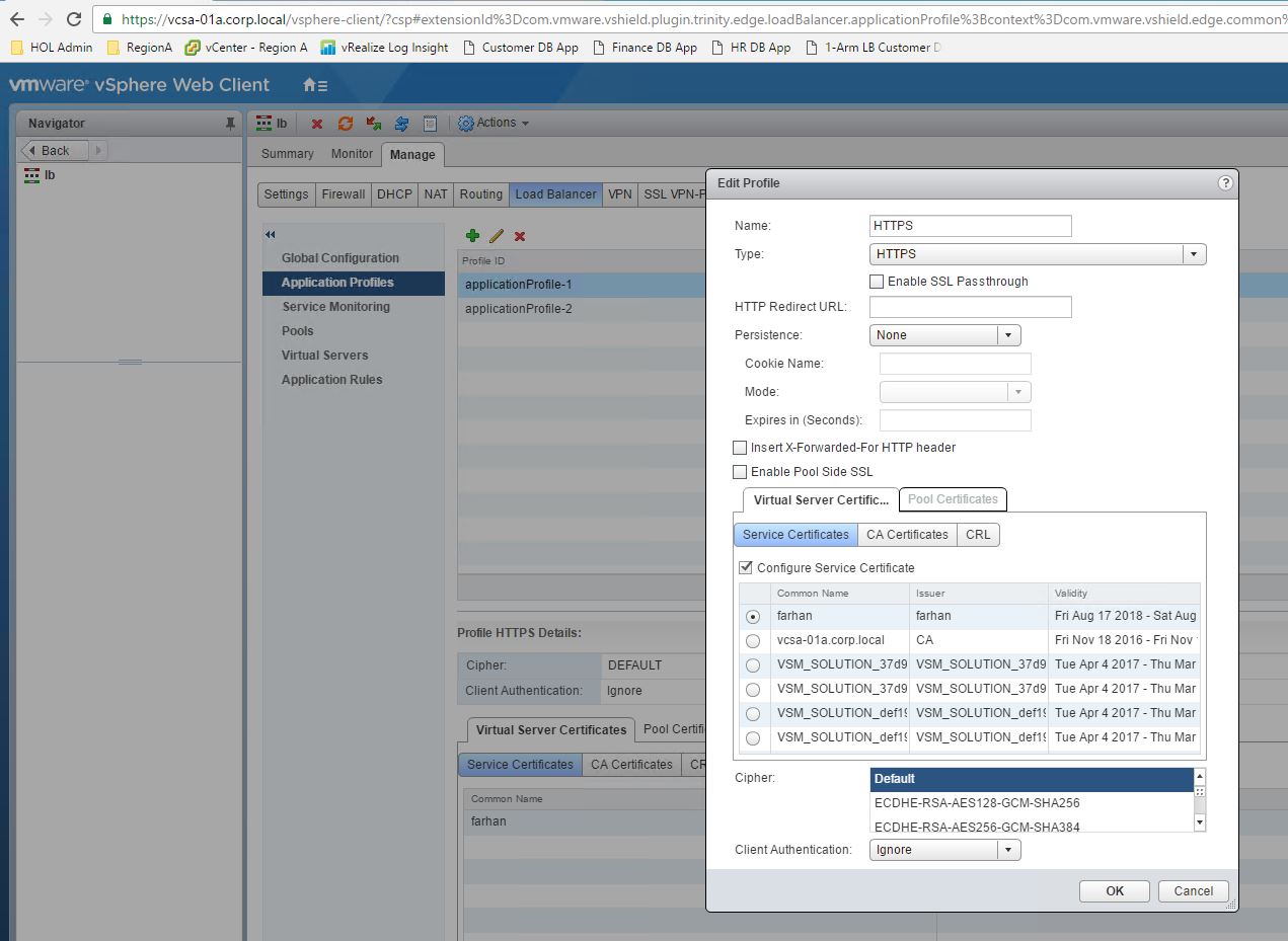
Application Profile
Application profile is created then and the details are as below
Application profile name - HTTPS
Application profile type – HTTPS
Certificate – For this lab setup, we have used a self-signed certificate.

Server Pool
Server pool is created as below
Pool name – pool
Algorithm – Round robin
Members – Virtual Machine web-01a, tcp/80
Members – Virtual Machine web-02a, tcp/80


Virtual Server

Virtual server is created using the secondary IP address and the virtual server details are as below
Virtual Server IP – 172.16.20.101
Virtual Server port – 443
Application Profile – HTTPS
Server pool name – pool

====================================


A management station is residing on the physical network with IP address as 192.168.110.10
We have also taken packet captures on the NSX Edge Load Balancer interface for below communications

  • Communication between the management station and the virtual server 172.16.20.101, tcp port 443
  • Communication between NSX Edge Load Balancer and the pool members.  


    Comm. between Mgmt. Station & Virtual Server


    Comm. between load balancer & pool members


It is worth noting that in the case when a secondary IP address 172.16.20.101 is assigned to single vnic of NSX Edge Load Balancer & the secondary IP address is used to create virtual server, the load balancer uses the primary IP address 172.16.20.100 to establish a connection between itself and the pool members.

Both the above packet captures are done at the same time while trying to access the web page at https://172.16.20.101
NSX Edge Load Balancer is working as a reverse proxy and from the packet captures, it is evident that there are two different TCP connections -
  1. One between initiator and load balancer 
  2. The other between load balancer and pool member
============================================================

NSX Edge Load Balancer supports below features:

1. SSL Offload
2. SSL Bridging
3. HTTP Profile with ‘insert X-Forwarded-For’
4. Cookie based persistence as well as source IP based persistence is supported.
5. Redirection from http to https
6. Multiple ciphers can be used.
7. Load balancing algorithms which are supported are:
  • Round robin
  • IP Hash
  • Least connection
  • URI
  • HTTPHEADER
  • URL 
=============================================================

Some very useful resources:

NSX Admin Guide
https://docs.vmware.com/en/VMware-NSX-for-vSphere/6.4/nsx_64_admin.pdf

NSX Reference Design Guide
https://www.vmware.com/content/dam/digitalmarketing/vmware/en/pdf/products/nsx/vmw-nsx-network-virtualization-design-guide.pdf