Thursday, April 9, 2020

NSX-T Multi Site

NSX-T Multi Site


NSX T Multi Site Topology

The above topology is for NSX-T Multi Site.
1. There are two Tier 0 Gateways provisioned.
One Tier 0 Gateway is in Primary Site.
The other Tier 0 Gateway is in DR site.

2. There is one DR only Tier 1 Gateway to which segments are connected.
Workload VMs are connected to these segments.
Tier 1 Gateway serves as the gateway for the workload VMs.
Tier 1 Gateway is connected to Tier 0 Gateway of Site 1.

3. Vcenter server and NSX-T Manager Cluster is on the stretched management cluster and the cluster is protected by vSphere HA.

4. Management network in which the vcenter server and NSX-T managers reside is stretched across both the sites.
This facilitates automatic recovery of management plane upon failure of Primary Site.

5. Segments are stretched across both the sites as a result there is stretched Layer 2 between both sites.
Workload VMs can vmotion across to the other site keeping the same IP address and the same Distributed Firewall security policy.

6. Two NSX-T Edge Clusters are present, one in each site.
Tier 0 Gateway of Site 1 uses the edge cluster of Site 1.
Likewise, Tier 0 Gateway of Site 2 uses the edge cluster of Site 2.

NSX-T Fabric Details:


Transport Zones
One overlay transport zone and three VLAN backed transport zones are defined.
Two VLAN backed transport zones are used for North-South peering between NSX edges and the physical routers.
Since the edges are using N-VDS on compute hosts for connectivity, a VLAN backed transport zone will be associated with compute hosts.

Separate subnets have been used for edge TEPs and TEPs on compute hosts.


Uplink Profiles

Uplinks profiles have been created for:
a. Edges in Site 1
b. Edges in Site 2
c. Compute hosts in Site 1
d. Compute hosts in Site 2


Compute TEP Pool Site 1

Compute TEP Pool Site 2

Edge TEP Pool Site 1

Edge TEP Pool Site 2
Pools have been defined for TEPs on edges and compute hosts:
a. TEP Pool for compute hosts in Site 1
b. TEP Pool for compute hosts in Site 2
c. TEP Pool for edge transport nodes in Site 1
d. TEP Pool for edge transport nodes in Site 2


Trunk Segments for connectivity of Edges
Two trunk segments have been created for connectivity of edges.


Segments for uplink interfaces on Tier 0 Gateway of Site 1


https://lets1learn2network.files.wordpress.com/2020/04/05a81-screen2bshot2b2020-04-102bat2b12.52.262bam.png
Segments for uplink interfaces on Tier 0 Gateway of Site 2


Segments are created using transport zones associated with edges.
These segments are used while creating uplink interfaces on Tier 0 Gateway.
Two segments are required for Tier 0 Gateway in Site 1.
Likewise two more segments are required for Tier 0 Gateway in Site 2.


Edge Transport Nodes and Transport Zone Association

Compute Transport Nodes and Transport Zone Association

Transport Zone Association:
- Hosts have transport zone ESXi as VLAN backed transport zone and Overlay transport zone associated.
- Edges have Overlay transport zones in addition to VLAN backed transport zones.


Host Transport Node Configuration in Site 1
Host transport nodes have single NVDS to handle overlay traffic as well VLAN backed traffic.
Compute TEP subnets are different in Site 1 and Site 2.
Host Transport Node Configuration in Site 2
https://lets1learn2network.files.wordpress.com/2020/04/69a6d-edge2btn2bconfiguration2bsite2b1.png
Edge Transport Node Configuration – Site 1 – EN 1

https://lets1learn2network.files.wordpress.com/2020/04/10037-edge2btn2bconfig2bsite2b2.png
Edge Transport Node Configuration Site 2 – EN 3


The  edge transport nodes are configured.
Trunk segments created on N-VDS of compute hosts are used as uplinks on the edges.
Appropriate uplink profiles and TEP pools are used.
Two different subnets are used for edge TEP interfaces in the two sites.


Edge Cluster in Site 1

Edge Cluster in Site 2
Two edge clusters have been created:
- One edge cluster for Tier 0 Gateway in Site 1
- Second edge cluster for Tier 0 Gateway in Site 2


Tier 0 Gateway in Site 1

Tier 0 Gateway in Site 2

Layer 3 interfaces on Tier 0 Gateway of Site 1


Layer 3 interfaces on Tier 0 Gateway of Site 2
Tier 0 Gateways are created:
- Tier 0 Gateway in Site 1
- Another Tier 0 Gateway in Site 2

Layer 3 interfaces are then created as above on each of the Tier 0 Gateway.


BGP Setup and routing configurations:


BGP Diagram

e BGP peering is used between edges and the physical routers.
BGP AS number 65000 is used within NSX and BGP AS number 65001 is used in the physical network.
The physical routers are sending default route towards the edges.
Routers in the physical network are configured with loopback networks
- 172.30.1.1 is loopback on physical router 1
- 172.30.2.2 is loopback on physical router 2

- 172.30.3.3 is loopback on physical router 3
- 172.30.4.4 is loopback on physical router 4

Physical routers 1 and 2 are in Site 1
Physical routers 3 and 4 are in Site 2

Full mesh i BGP is used between the physical routers in this lab setup.
Usage of route reflectors is recommended in production networks instead of a full meshed i BGP setup to reduce the number of i BGP peerings, also to optimize physical router resources.

North South traffic flow under normal operations is through Primary Site 1.
Tier 1 Gateway is connected to Tier 0 Gateway of Site 1 during normal operations.


Setup BGP AS number on Tier 0 Gateway

BGP peers on Tier 0 Gateway of Site 1
BGP configuration is applied on both Tier 0 Gateways.
Here BGP AS number is defined.
And also appropriate BGP peers are defined.


Advertise connected subnets on Tier 1 Gateway

Redistribution settings on Tier 0 Gateway of Site 1

Redistribution settings on Tier 0 Gateway of Site 2
Enable route redistribution on Tier 0 Gateways to redistribute NSX routes into BGP

Traffic Flows during normal operations

Traffic flow during normal operations through Primary Site 1


Under normal operations, North South traffic flow will be through Site 1/Primary Site as shown above.


Routing table on Tier 0 SR on Edge Node 1 - Site 1
BGP peerings on Tier 0 SR of Edge Node 1 are up.
This Tier 0 SR is learning default routes from upstream physical routers.
It is also learning the loopback networks defined on each physical routers because those are advertised via BGP.


VM on segment is able to reach the loopback networks on physical routers
Trace from Site 1 physical router to VM on segment

Trace from Site 2 physical router to VM on segment

Failover/DR scenario:


Traffic flow through DR site

The primary site has failed.
So the physical routers in primary site are down.
Edges in primary site are also down.

Now the DR only Tier 1 Gateway has to be connected to Tier 0 Gateway of Site 2 to influence traffic flow through Site 2.


Tier 1 Gateway is connected to Tier 0 Gateway of Site 2


Trace from loopback on physical router of Site 2 to VM on segment

Now verify the traffic flow by sourcing traffic from loopback network on physical router of Site 2.

Workload VM can reach loopbacks of physical routers in Site 2
Notice from the above output that workload VM can reach loopback networks of physical routers in Site 2 but is unable to reach loopback network of physical router 1 since router 1 is down.


Saturday, March 14, 2020

Load Balancing in NSX-T


Load Balancing in NSX T

Reference:

This post covers the configuration required to use load balancer which is a native feature in NSX-T.

Pre requisites before configuring load balancer:

1. NSX T Manager Cluster should be deployed
2. Transport zones should be defined.
3. Uplink profiles should be created.
4. Hosts should be configured as Host Transport Nodes.
5. Edge Transport Nodes should be deployed and configured.
6. Edge Cluster should be created.
7. Tier 0 Gateway should be created and peering with physical network should be in place.

Logical Topology for Load Balancing

As shown in the above topology, one Tier 0 Gateway aggregates the connections from two Tier 1 Gateways.
There is one Tier 1 Gateway dedicated for load balancing service.
The other Tier 1 Gateway is where the workloads are connected via segments.
Tier 1 Logical Router 2 is a DR only Logical Router/Gateway to which workload segment is connected.

Tier 0 Gateway peers with the physical network and hence always requires edge cluster.
In this lab, we will use the same edge cluster for Tier 0 Gateway and for the Tier 1 Gateway used for load balancing service.

If sufficient resources exist, then dedicated resources can be provided for load balancing service and as such a separate edge cluster can be created which will be used only for services viz. load balancing.


DR only Tier 1 Gateway

As shown above, this Tier 1 Gateway is a DR only Tier 1 Gateway.
Segments for workloads are connected to this Tier 1 Gateway.
This Tier 1 Gateway is not associated with any edge cluster.

The DR only status of Tier 1 Gateway can also be verified using the below command on CLI of the edge node.

DR Only Tier 1 Gateway


The above Tier 1 Gateway is used for load balancing purpose.
Load balancing service requires presence of edge cluster.
As you can see, edge cluster is associated with this Tier 1 Gateway.
Also note that from route advertisement perspective, we are advertising LB VIP routes and LB SNAT IP Routes from this Tier 1 Gateway.
 
Communication between Virtual Server and the servers
The above diagram shows the communication between LB Virtual Server IP address 172.16.40.6 and the back end servers.
LB Virtual Server IP 172.16.40.6 is also used as SNAT IP address because the load balancer is in one arm mode. One arm mode of load balancer requires SNAT because the back end servers will then respond back to the SNAT IP.


Configuration of Load Balancer:

Here we are going to configure Layer 4 TCP based load balancing.

Server pool is defined as follows.

Server Pool Configuration

Server Pool Members
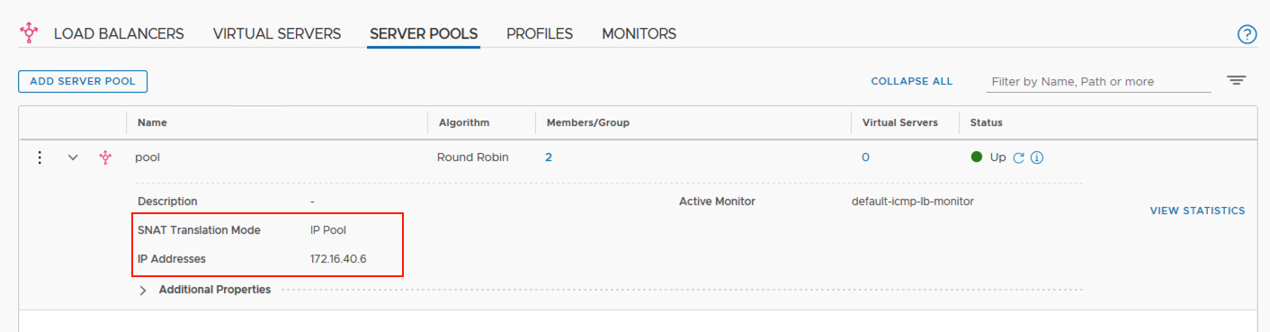
As shown above, server pool is created.
Please note that SNAT configuration has been applied while creating the server pool and the SNAT IP has been kept as the virtual server IP 172.16.40.6

Server pool members are configured.

Next, create a load balancer and associate Tier 1 Gateway 'T1-LB' with this load balancer.

Create load balancer
Note that the load balancer size here is kept as small, this is just for lab purpose.
We need to keep in mind the configuration maximums for each load balancer size.


Load balancer size depends upon the size of the edge node deployed.
If the size of the edge node is large, then one large sized load balancer can be created.
1000 virtual servers can be created for Large sized load balancer.

Next, create a virtual server.
Create Virtual Server


Associate Virtual Server with server pool

Status of Virtual Server
Using above, virtual server status can be verified using the UI.
 
Troubleshooting using CLI:


High Availability Status on Edge Node

Using the above commands, you can verify which edge node is 'Active'.
As seen, for the service router SR-T1-LB, edge node 'edgenode-01a' is Active.
 
You can get UUID of Load Balancer using the Advanced UI:
UUID of Load Balancer

Using this UUID, you can execute below commands on the Active edge node to display the server pool status and the status of virtual server.


Server Pool Members Information using CLI


Virtual Server Status and information


Saturday, January 4, 2020

Connecting NSX-T Tier 0 Gateway to another Tier 0 Gateway

Connecting NSX-T Tier 0 Gateway to another Tier 0 Gateway

Reference : NSX-T Design Guide

A Tier 0 Gateway is typically required to connect to the physical network.
A Tier 1 Gateway in NSX-T does not connect to the physical network directly.
Segments to which workloads are attached are connected to Tier 1 Gateways.

Tier 0 Gateway is called a provider gateway and Tier 1 Gateway is called as tenant gateway.

In this post, we will explore the configurations required to connect NSX-T Tier 0 Gateway to another Tier 0 Gateway.
This addresses the use case where multiple Tier 0 Gateways need to connect to one Tier 0 Gateway which can possibly consist of 8 Edge Nodes for 8 way ECMP.

One may note that it is possible to use Active-Active or Active-Standby availability mode on the Tier 0 Gateway.
In this lab set up, both the Tier 0 Gateways have been configured in Active-Active High Availability mode.

Lab Topology

As shown in the figure above, two Tier 0 Gateways have been created using four edge node VMs.

Tier 0 Gateways are named as Tier 0 Gateway Up and Tier 0 Gateway Down respectively.

A Tier 1 Gateway is connected to Tier 0 Gateway Down.
A segment is attached to this Tier 1 Gateway with a corresponding subnet of 172.16.10.0 / 24

Physical routers upstream connect via VLANs to the the edge node VMs.


IP Addressing and BGP Diagram

The above diagram shows the IP addressing used in this lab topology along with the BGP Peerings.

BGP AS Number 65000 is used on the Tier 0 Gateways.
BGP AS number 65001 is used on the physical routers.
The physical routers are advertising default routes towards the NSX edges.

NSX-T Fabric Preparation:


Transport Zones
Four transport zones have been defined as above.
Edge Transport Nodes corresponding to edge cluster used for Tier 0 Gateway Down will only have the Overlay Transport Zone.


Edge Transport Nodes corresponding to edge cluster used for Tier 0 Gateway Up will have overlay transport zone, VLAN-1 transport zone and VLAN-2 transport zone.


Uplink Profile for Edge Node VMs


The uplink profile for edge has VLAN ID as 4 which is for Tunnel Endpoint TEP Interfaces on the edge node VMs.
Tunnel Endpoint interfaces on Transport Nodes are used to establish Geneve tunnels between each other.

The VLAN ID 2 for TEP interfaces on compute hosts is different because the edge node VMs of Tier 0 Gateway Up use the N-VDS of compute for connectivity.


Uplink Profile for Compute Hosts

Note the VLAN ID in this compute uplink profile is set as 2


Compute Host Transport Nodes
Compute Host Transport Nodes are prepared as above.
ESXi transport zone is VLAN backed transport zone used to host VLAN backed segments. VLAN backed segments have been used to attach to fast path interfaces of edge node VM.
This has been covered in my post here.

Edge Transport Nodes

Edge Cluster for Tier 0 Gateway Up

Edge Cluster for Tier 0 Gateway Down

Gateway and Interface Configuration:

Tier 0 Gateways

Using the two edge clusters created earlier, we have created two Tier 0 Gateways -
T0 DOWN
T0 UP

Segments used for connecting Tier 0 Gateways to each other

Overlay backed transport zone is used to create four overlay segments and these segments will be used for connecting the Tier 0 Gateways to each other as shown in the lab topology earlier.


Layer 3 interface configurations on Tier 0  Gateway Up

Layer 3 interface configurations on Tier 0  Gateway Up (Note the edge nodes used)


Layer 3 interface configurations on Tier 0  Gateway Down

Routing Configuration:

BGP configuration is done next on the physical routers and the Tier 0 Gateways.
Please follow the BGP diagram above for the BGP peerings.
Source Addresses are used to source BGP session from appropriate interface only.
 

BGP Neighbor Configuration on Tier 0 Gateway Down

BGP Neighbor Configuration on Tier 0 Gateway Up


Distributed Router only Tier 1 Gateway with no edge cluster association

Connected routes on Tier 1 Gateway are advertised towards upstream Tier 0 Gateway Down.


Redistribute connected interfaces and segments on Tier 0 Gateway Down

Redistribute connected interfaces and segments on Tier 0 Gateway Up

Validation:


BGP Peering on physical router TOR1

BGP peering on TOR2 physical router


BGP Peerings on Edge Node VM 1 which belongs to Tier 0 Gateway Up

Notice that there is BGP peering between two edge nodes which are forming the Tier 0 Gateway, this is because we have enabled Inter SR iBGP


From the above output, we see that the physical router is able to reach 172.16.10.1 with 1500 bytes size.
This IP 172.16.10.1 is configured as gateway for the segment attached to Tier 1 Logical Router.